
delabs circuits
Electronic Engineering Schematics
Function Generator using ICL8038 and XR-2206 - del50005
ICL8038 and XR-2206 can help you build a Function Generator or Wavform Generator. It is needed along with the Oscilloscope and Power Supply on the Workbench.The ICL8038 waveform generator is a monolithic integrated circuit capable of producing high accuracy sine, square, triangular, sawtooth and pulse waveforms with a minimum of external components. The frequency (or repetition rate) can be selected externally from 0.001Hz to more than 300kHz using either resistors or capacitors, and frequency modulation and sweeping can be accomplished with an external voltage.
Use in Phase Locked Loops - Its high frequency stability makes the ICL8038 an ideal building block for a phase locked loop as shown in Figure 9. In this application the remaining functional blocks, the phase detector and the amplifier, can be formed by a number of available ICs (e.g., MC4344, NE562).
ICL8038 Versatile Waveform Generator
delabs Notes - This was one of my favorite chips. This is of educational value. It was a pioneer chip a mixed cmos device. Make it a point to read the Datasheet. Chip may have been invented 1980 around. This is study material for college. It is not available in stores. Some EE Engineer or Ham-DIY Enthusiast may have a few. Borrow and try it out for learning.
Function and Waveform Generators – IC
Science Fiction - Advanced Students can try configuring it in a Programmable Mixed Chip EDA tool plugin, if someone has developed that. Try taking a draft output on a semiconductor laser nano-milling prototype printer with a built in Mems pico-doper. If that works, lets go foundry! Forgot to tell you, Sprinkle Gallium Arsenide in the RF Areas, and add Graphene to taste
Specifications
Frequency range - 0.95 Hz to 105 KHz in five decade ranges.
Waveforms - Sine, Triangular and Square.
Output amplitude - Adjustable from 10 mV PP. to 10 V PP Output impedance 50 ohms.
Sine wave Amplitude Flatness +/- 1 dB
Sine wave THD
- Less than or equal to 0.8% from 10 Hz to 10 KHz
- Less than or equal to 2.5% from 1 Hz to 100 KHz
- Less than or equal to 0.5% upto 10 KHz.
- Less than or equal to 1.5% at 100 KHz.
Components
SEMICONDUCTORS - IC1-ICL8038, IC2-LM318, T1-SL100, T2-SK100, D1, D2-IN4148
RESISTORS - 1/4 W - 5% R1, R13, R14-10E; R18-22E; R16-47E; R11-56E; R9-220E; R19-390E; R2-1KE; R6, R8-2.2KE; R17-1.8KE; R3-R5-4.7KE; R10, R29, R15-3.9KE; R20, R21-39KE; R22-15KE.
PRESETS - VR1, VR3-2.2KE; VR4-470E; VR5-VR7-l00KE; VR8-22KE; VR10-IOKE.
POTENTIOMETERS - VR2-FF-500E 1 W, VR9-VF-22K 1 W.
CAPACITORS - 30V C1, C7, C8,-0.1 MFD; C2-3.3 MFD; C3-0.33 MFD; C4-33 KPF; C5-3.3 KPF; C6-330PF; C9-100MFD; C10-22PF; C11, C12-IOKPF; C13-20KPF.
Panel-Parts - FC-1 POLE 5 WAY SWITCH, SS-2 POLE 3 WAY SWITCH, VC-1 POLE 4 WAY SWITCH, PCB, KNOBS, 2BNC SOCKETS, E,F IC BASES.

Electronics - ICL8038-based Oscillator - The ICL8038 and all parts around on the lower half of the sheet make up the actual oscillator which is a modified design based on one of the application examples in Intersil's data sheet. There is a large 6-stage switch (S1) to select the major frequency and a logarithmic potentiometer (R2) for minor frequency selection.
A High Quality Function Generator system Using the XR-2206 - Application Note AN-14
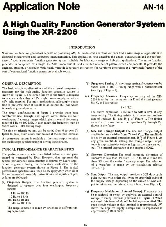
Waveform or function generators capable of producing AM/FM modulated sine wave outputs find a wide range of applications in electrical measurement and laboratory instrumentation. This application note describes the design, construction and the performance of such a complete function generator system suitable for laboratory usage or hobbyist applications. An old Datasheet of XR-2206

The basic circuit configuration and the external components necessary for the high-quality function generator system is shown in Figure 1. The circuit shown in the figure is designed to operate with either a 12V single power supply, or with a ±6V split supplies. For most applications, split-supply operation is preferred since it results in an output DC level which is nearly at ground potential.
The circuit configuration of Figure 1 provides three basic waveforms: sine, triangle and square wave. There are four overlapping frequency ranges which give an overall frequency range of 1 Hz to 100 kHz. In each range, the frequency may be varied over a 100:1 tuning range.
- Function Generator system Using the XR-2206 - Page 1
- Function Generator system Using the XR-2206 - Page 2
- Function Generator system Using the XR-2206 - Page 3
- Function Generator system Using
the XR-2206 - Page 4
...
...
...
...
...
delabs Technologies
20th Mar 2020
...
Disclaimer and Terms of usage
The documents, software, tools and links are provided to enhance the ability of an electronics student, hobbyist or professional by sharing information. The information, links etc. should be used by the website visitor, at his or her own risk and responsibility. There may be concept, design and link errors in the pages.
Creative Work, ideas and documents of delabs can be used for Product Design and Development by R&D Engineers, Hobbyists, Students and even firms for creating useful products. These cannot be used for reprint, replication or publishing online or offline.